Materials expand when heated and contract when cooled. Pipes are not immune to these laws of nature, so they will also expand and contract with varying temperature.
This article will introduce the basics of stresses and anchor loads induced by thermal expansion. To stick to the basics, a straight piece of restrained pipe will serve as the example. We will also look at some available options to reduce the pipe stresses and anchor loads.
Stresses Induced by Thermal Expansion-The Basics
We will start with some definitions of commonly used flexibility terms. Stress is defined as force per unit area in a material:
S = F/A (Equation 1)
S = Stress (psi-can be negative or positive)
F = Force (lbf-can be negative or positive)
A = Area (square inches)
Strain is defined as a percentage or ratio of a change of length divided by the original length:
ε = ΔL/Lo (Equation 2)
ε = Strain (inch/inch-can be negative or positive)
ΔL = Change in length (inches-can be negative or positive)
Lo = Starting length (inches)
Stress and strain are related by Hooke’s Law:
S = Eε (Equation 3)
S = Stress (psi)
E = Young’s Modulus (psi)
ε = Strain (in/in)
Piping materials exhibit nearly linear expansion and contraction with temperature. The rate of thermal expansion and contraction is characterized by the coefficient of thermal expansion, a, and has units of in/in-°F, or strain per degree Fahrenheit. The change in dimensions of an object is then:
ε = a (T2-T1) (Equation 4)
ε = strain (in/in)
a = Coefficient of thermal expansion (in/in-°F)
T2 = End temperature (°F)
T1 = Starting temperature (°F)
If the object is a straight bar or pipe, the more familiar form of this equation is:
ΔL = aLo(T2-T1) (Equation 5)
ΔL = Change in length (in)
Lo = Initial length of pipe (in)
Consider a 6 in diameter steel (ASTM A53) pipe, 100 ft long, anchored at one end. The pipe is empty, and the inside is at atmospheric pressure. The temperature is increased to 200 deg F above ambient. The expansion of the pipe from equation (2) is:
a = 6.33 x 10⁻⁶ in/in-°F
Lo = 1,200 in
T2 = 270 deg F
T1 = 70 deg F
ΔL = (6.33 x1 0-6 in/in-°F)(1,200 in)(270°F-70°F)
= 1.52 in
If the pipe is installed at an ambient temperature of 70 deg F, and the temperature of the pipe increases to 270 deg F, we can expect about 1.5 in of expansion in the 100 ft unanchored run. Assuming the pipe is properly supported along its length, the stresses will remain well below the yield point of the steel.
If the pipe is now anchored at both ends and subjected to the same conditions, the stresses in the pipe will significantly increase. The anchors will prevent the pipe from expanding during the temperature rise. The result will likely be failed anchors, a buckled pipe or both.

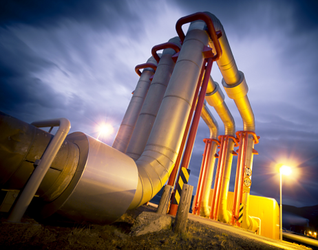
Figure 1. The anchor forces in a 6 in. pipe undergoing thermal expansion
The pipe is in static equilibrium, but the only forces acting on it are the pipe anchors (static indeterminacy). The material properties can tell us how much force and stress will build in the pipe. The reaction force of the anchor must equal the amount of force needed to contract the pipe by 1.5 in (the amount of thermal expansion).
Substituting equations 1 and 4 into equation 3, stress is related to thermal strain by:
F/A = Ea (T2-T1) (Equation 6)
To solve for the force in the anchors, equation 6 can be rearranged as:
F = AEa (T2-T1) (Equation 6)
Notice that the initial length and change in length do not matter in calculating the stresses and forces. For our 6 in diameter, 100 ft pipe restrained by the anchors:
A = 5.581 in2
E = 27.5 x 10⁶ lbf/in2
a = 6.33 x 10⁻⁶ in/in-°F
T2 = 270 deg F
T1 = 70 deg F
The stress along the longitudinal axis of the pipe is then:
S = Ea (T2-T1)
= (27.5 x 10⁶ lbf/in2)(6.33 x 10-6 in/in-°F)(270°F-70°F)
= 194,315 lbf/5.581 in2
= 34,815 psi
The force in the anchors is:
F = stress x pipe area
F = (5.581 in2)(34,815 lbf/in2)
= 194,315 lbf (anchor load)
If the pipe has a 2 in diameter, the area is 1.075 in2, the reaction force is 37,410 lbf and the resulting axial stress would be the same, 34,815 psi. The stress in this simple case only depends on the material properties and the temperature change; however, the anchor loads are also dependent on the pipe section dimensions.

Table 1. Comparison of the anchor forces for different pipe dieameters (straight pipe only)
- See more at: http://www.pump-zone.com/topics/piping/basics-pipe-thermal-expansion#sthash.rFYrLdMn.dpuf
Source:
http://www.ccop.or.th/download/PETRAD/PETRAD58_2011-01/Paper09_ZamriAhmad-PETRONAS-PMU.pdf
 Popular
 Tags
Tags Videos

0 comments:
Post a Comment